Sizing a Compact Wheel Motor by Load, Speed and Wheel Diameter
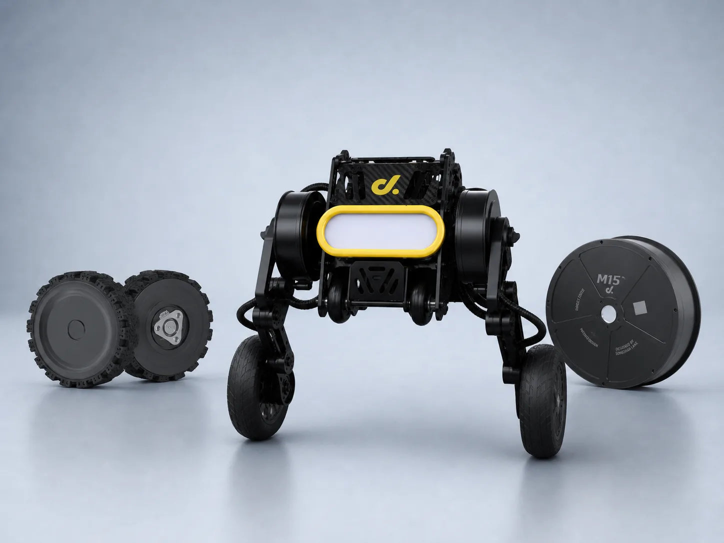
Sizing a compact wheel motor requires matching three physical parameters: vehicle load, target speed, and wheel diameter. For a 60 kg mobile robot with 150 mm wheels, typical requirements range from 2–5 N·m continuous torque and 100–250 W mechanical output depending on slope and terrain. A 20% increase in wheel diameter can raise torque demand by about 20% because torque is proportional to wheel radius. Motor selection should consider continuous torque, peak torque, RPM, gearbox ratio, and thermal limits rather than only rated wattage.
Wheel motor selection begins with the total mass supported by the platform. The design mass includes the chassis, battery, sensors, payload, and mechanical components. A robot listed at 50 kg may require calculations based on 75–100 kg equivalent loading when acceleration, uneven floors, and climbing conditions are included. Many mobile robot manufacturers apply a safety factor between 1.3 and 2.0, depending on operating conditions and duty cycle.
A robot operating on smooth indoor floors may use a lower torque margin, while an outdoor inspection robot facing slopes, gravel, or thresholds often requires 50–100% additional torque capacity.
The next calculation is traction force. The wheel must generate enough force to overcome rolling resistance, incline resistance, and acceleration requirements. The total force requirement can be estimated from:
| Resistance type | Typical range |
|---|---|
| Indoor rubber wheel rolling resistance | 0.01–0.03 of vehicle weight |
| Outdoor uneven surface resistance | 0.05–0.15 of vehicle weight |
| Moderate climbing slope | Additional 10–30% force requirement |
For a 80 kg robot climbing a 10° slope, the gravitational component alone requires approximately 136 N of additional traction force. With 100 mm radius wheels, this produces around 13.6 N·m torque before considering gearbox losses. A motor system with 85% transmission efficiency would require approximately 16 N·m output torque to maintain the same performance.
Wheel diameter changes the motor requirement significantly. Small wheels between 50 mm and 100 mm are common in indoor robots because they reduce torque demand and allow compact designs. Medium wheels from 100 mm to 200 mm are frequently used in autonomous mobile robots because they provide better floor clearance while maintaining manageable motor size. Wheels above 250 mm improve outdoor mobility but require larger gear reductions and stronger mechanical structures.
Increasing wheel diameter from 100 mm to 200 mm doubles the wheel radius, meaning the motor must provide approximately twice the torque for the same driving force.
Speed conversion is another important part of motor sizing. Vehicle speed is converted into wheel rotational speed using wheel circumference. A robot traveling at 1.5 m/s with 150 mm diameter wheels requires around 191 RPM at the wheel. The same vehicle using 300 mm wheels requires about 95 RPM. This difference affects gearbox selection because many compact brushless motors operate efficiently between 2000 and 6000 RPM.
A gearbox allows a high-speed motor to produce useful wheel torque. For example, a motor producing 0.5 N·m torque at 4000 RPM combined with a 30:1 gearbox can theoretically generate 15 N·m output torque. After considering gearbox efficiency, typically 80–95% for planetary systems, the actual output may be closer to 12–14 N·m. Planetary gearboxes are widely used in robotics because they provide high torque density in a compact package.
The relationship between torque, speed, and power determines the motor rating. Mechanical power can be estimated from torque and angular velocity. A wheel motor producing 5 N·m torque at 200 RPM requires about 105 W mechanical output. With controller losses, gearbox losses, and thermal limitations included, a motor rated around 150 W may provide a practical continuous operating range.
Motor manufacturers often separate continuous torque and peak torque ratings. Continuous torque represents the output that can be maintained without exceeding temperature limits, while peak torque is usually available for acceleration or short obstacles. A motor that provides 10 N·m peak torque but only 3 N·m continuous torque may not be suitable for a robot climbing slopes for several minutes.
Thermal management strongly affects compact motor performance. Copper winding losses increase with the square of current. When current increases by 50%, copper heating can increase by approximately 125%. For this reason, compact motors operating near maximum current require aluminum housings, heat paths, and proper duty cycle control. Many robotic systems limit continuous operation to 60–80% of rated current to maintain long service life.
Modern robotic platforms increasingly use integrated wheel systems combining motor, gearbox, encoder, and controller. These systems reduce wiring complexity and save installation space. Compact integrated units are often used in warehouse robots, medical robots, and inspection platforms where installation volume is limited. Products such as small robot drive modules combine compact motor structures with feedback systems for precise speed and position control.
The selection process can be organized through several design steps:
| Design parameter | Calculation method | Example value |
|---|---|---|
| Vehicle mass | Include payload and safety margin | 80 kg |
| Wheel diameter | Determine torque requirement | 150 mm |
| Target speed | Convert to wheel RPM | 1.5 m/s ≈ 191 RPM |
| Required torque | Force × wheel radius | 5–10 N·m |
| Motor power | Torque × rotational speed | 100–200 W |
Acceleration requirements also affect motor choice. A robot accelerating from 0 to 2 m/s within 3 seconds requires additional force beyond normal cruising conditions. For a 100 kg platform, acceleration alone requires about 67 N force. If the wheel radius is 0.075 m, this adds approximately 5 N·m torque requirement. A motor selected only for constant-speed travel may fail during frequent starts and stops.
Environmental conditions influence the final motor specification. Indoor robots may operate 90% of the time on flat surfaces with low resistance, while outdoor robots may experience rain, dust, and uneven terrain. Sealed motors with IP65 or higher protection are commonly selected for outdoor applications. Temperature ranges from -20°C to 50°C are often considered in industrial mobile robot designs.
In 2025, autonomous warehouse robots commonly used wheel motor systems between 100 W and 500 W depending on payload class. Small inspection robots below 20 kg often operate with motors under 100 W, while logistics platforms carrying several hundred kilograms may require multiple high-torque wheel modules. The number of driven wheels also changes motor sizing because a four-wheel drive system distributes torque differently from a two-wheel configuration.
Battery selection must also match motor requirements. A 200 W wheel motor operating continuously for 4 hours requires at least 800 Wh mechanical energy before considering efficiency losses. With an overall electrical efficiency of 75%, the battery requirement increases to more than 1000 Wh. Oversized motors can therefore increase battery capacity requirements and vehicle weight.
A properly sized compact wheel motor balances torque, speed, wheel diameter, efficiency, and thermal performance. Calculating these parameters before selecting hardware allows the motor to operate within its designed range and provides stable movement across different operating conditions. For compact robotic systems, matching the wheel motor specification with the actual mechanical requirements is the basis for reliable long-term operation.