How Do You Determine the Correct Length for custom hydraulic hoses?
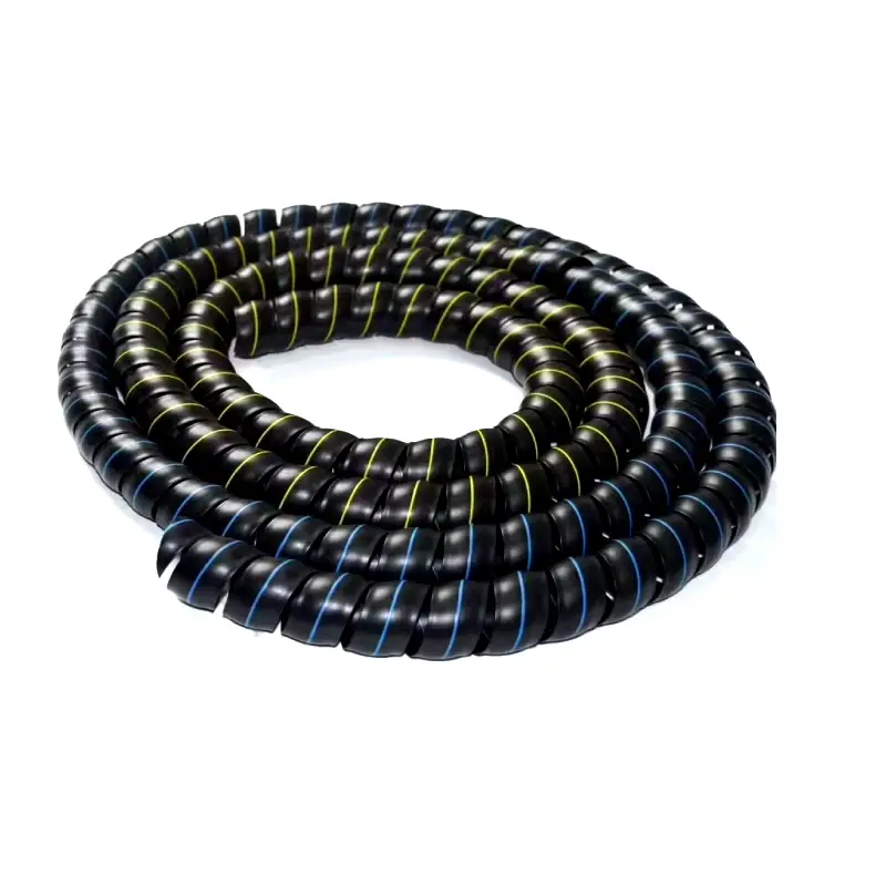
The correct length for a custom hydraulic hose comes from the installed route, not the straight distance between ports. Measure from the specified fitting reference points, then account for minimum bend radius, machine travel, fitting orientation, pressure-related length change, and free hose near each coupling. Parker notes that some hydraulic hoses may change length by as much as +2% to -4% under pressure, so a 2,000 mm assembly could shift by 40–80 mm. Gates also specifies that bend diameter must remain at least 2 times the hose’s minimum bend radius. Measure the machine at both ends of its travel before ordering.
Start with the route the hose will actually follow. A 900 mm straight-line distance can require a 1,100–1,300 mm assembly once the hose passes around a frame member, enters a clamp, clears a valve block, and approaches a port without a sharp bend. A flexible tape, soft tubing, or the removed hose can reproduce the centerline more accurately than measuring between the ports with a rigid ruler.
Treat the measurement as a three-dimensional installed path. If the machine moves, measure the path again at full extension, full retraction, and at least one middle position.
Pressure changes the geometry after installation, so static fit alone is not enough. Parker’s hydraulic guidance states that hose length under pressure may change by as much as +2% or -4%, depending on construction. A 1,500 mm hose shortening by 4% loses 60 mm; a 3,000 mm assembly loses 120 mm. An assembly installed tightly at zero pressure may therefore pull against the coupling when the system reaches operating pressure.
That pressure allowance should not be replaced by random extra hose. Gates states that an assembly that is too short may not accommodate flexing or pressure-related expansion and contraction, while excessive length adds unnecessary hose and can worsen routing. The practical target is enough free length for movement without creating a loose loop that can rub, sag, or enter nearby moving parts.
| Measurement item | What to record | Example |
|---|---|---|
| Port-to-port distance | Initial reference only | 1,000 mm |
| Routed centerline | Actual hose path | 1,180 mm |
| Machine travel | Maximum relative movement | 250 mm |
| Minimum bend radius | Hose datasheet value | 100 mm |
| Pressure length change | Manufacturer specification | +2% / -4% |
| Fitting orientation | Angle between elbows | 0°, 90°, 180° |
Once the route is known, check the bend radius before approving the length. Gates specifies that dimension “A,” the smallest bend diameter in an actuating installation, must not be less than 2 times the hose minimum bend radius. If a hose has a 100 mm minimum bend radius, the corresponding bend diameter cannot be below 200 mm. Adding another 100 mm of hose will not fix a route that still forces the hose around a 70 mm radius.
Real product data shows why one general bend allowance does not work. A Gates 3/4-inch M2T SAE 100R16 hose lists a 96.5 mm minimum bend radius and 3,500 psi working pressure, while a 1-1/4-inch version lists a 210 mm minimum radius and 2,300 psi working pressure. The larger hose therefore needs more physical space even when both products belong to the same hose family.
The straight section beside each coupling also needs attention. Gates recommends that bending should not begin less than 1.5 times the hose diameter from the hose end in its installation guidance. Its assembly-length guidance further states that the free length near a coupling, identified as dimension “B,” should not be less than 2 times the hose outside diameter while also allowing for full actuation travel.
For a hose with a 35 mm outside diameter, 2 times OD is 70 mm. That space helps move bending away from the coupling transition. If the port sits only 30 mm from a frame wall, ordering a longer hose alone may still leave poor geometry; changing from a straight connection to a 45° or 90° adapter may give the hose a usable departure direction.
-
Measure overall assembly length using the fitting maker’s stated reference points.
-
Record both fitting styles instead of describing only the hose body.
-
Record elbow orientation when 2 angled fittings are used.
-
Check the route at 3 or more machine positions when components articulate.
-
Compare the measured bend with the exact minimum radius listed for that hose size.
-
Leave enough free hose for pressure movement without creating uncontrolled loops.
Fitting reference points can change the final number by several centimeters. Gates describes assembly length as overall length, commonly measured from cone face to cone face; where elbow couplings are used, the centerline of the cone face becomes part of the measurement convention. Measuring only the exposed rubber section can therefore produce the wrong replacement even when the old hose is lying on the workbench.
This becomes more important with two elbows. A 1,200 mm assembly with two 90° fittings can still be unusable if the second fitting is rotated 90° away from the required port position. Length and angular orientation should be recorded together before crimping, because twisting the hose during installation to correct an elbow position adds torsional stress. Gates advises installing hoses without twist and warns that pressure on a twisted assembly can contribute to failure or connection loosening.
Moving machinery requires another measurement pass. A cylinder hose may look relaxed with a 300 mm stroke fully retracted but become tight during the final 50 mm of extension because the port does not move in a straight line relative to its anchor point. Steering systems, loader arms, forklift masts, agricultural implements, and articulated equipment can also change both distance and hose angle during travel.
Cycle the mechanism through 100% of its intended movement before freezing the hose length. Watch the fitting ends, the smallest bend, clamps, frame edges, and any location where the hose changes direction.
Clamps should control the route without stopping the hose from accommodating pressure-related movement. Gates advises against clamping at bends where the curve needs to absorb length change and recommends correctly sized clamps on long runs to reduce rubbing and abrasion. A clamp that is too large can let the hose move inside it; placing a rigid clamp immediately beside a working bend can restrict the movement the extra hose was intended to provide.
Temperature and operating pressure should be checked before the final measurement is approved because the selected hose construction determines how much freedom the installation needs. Parker notes that rated hydraulic-hose data is tied to specified service conditions and states that many hose products use a 1:4 relationship between recommended working pressure and minimum rated burst pressure unless the product specification says otherwise. A hose rated at 3,000 psi under that convention may therefore have a minimum burst rating around 12,000 psi, but assembly routing still has to meet the maker’s installation limits.
Replacement work also needs a condition check before copying the old assembly. A hose removed after years of service may have been stretched, flattened near a clamp, permanently curved, or installed incorrectly from the beginning. Instead of copying a 1,460 mm failed hose automatically, compare its relaxed length with the machine route and the original fitting locations. A difference of only 3% equals almost 44 mm on a 1,460 mm assembly.
When there is no reliable old hose, a physical mock-up is usually more useful than estimating a percentage. Run flexible tubing or rope through the planned route, mark the two fitting reference locations, move the equipment through its full range, and then measure the marked path. A 10% allowance should not be added automatically; an extra 100 mm on a 1,000 mm stationary line may simply create a rubbing loop, while a moving application may require much more than 100 mm.
The same measurement process should be communicated clearly to the fabricator. A qualified industrial hose manufacturer normally needs more than a single length number: hose ID or dash size, pressure rating, fitting type at both ends, thread or flange style, sealing face, overall assembly length, elbow orientation, fluid, temperature range, and intended movement all affect whether the finished assembly fits the machine.
For example, Gates lists a 1-inch M2T SAE 100R16 hose at 2,500 psi working pressure, 114.3 mm minimum bend radius, 25.4 mm ID, and 35.3 mm OD. If that hose is used in a moving U-shaped route, a bend diameter below 228.6 mm would conflict with the manufacturer’s 2-times-radius guidance, while the free hose near the coupling also has to respect the dimensional guidance for the assembly.
A final shop measurement can therefore be written as a compact specification rather than “make it about 1.5 meters long”: 1,520 mm overall length, 25.4 mm ID, 2,500 psi or higher working rating, 114.3 mm minimum bend radius or better, specified end connections, recorded elbow clocking, and verified clearance through 100% of machine travel. That level of detail gives the fabricator dimensions that can be checked before crimping instead of correcting fit at installation.